

The problem
Whenever you use a development board for a micro controller you will assign some pins. It could be something simple such as an output pin to control an LED, it could be pins for a UART connection, an ADC, or many other things. At some point you will need to connect these pins to your hardware by connecting some cables or soldering connections. And here is where it can get complicated. If you have a sufficiently large number of pins you want to connect, this can become quite time-consuming. To connect a cable you have to
- know the pin name and its function
- find the pin on the schematics of the development board
Since a dev board can have a huge number of pins it can take a significant amount of time to find a pin. This is amplified by the fact that pins can have alternate names and sometimes certain pins are not available on a header even though the micro controller has that pin in theory.
To give you an example here is an image of the assigned pins to a STM32F429 micro controller.
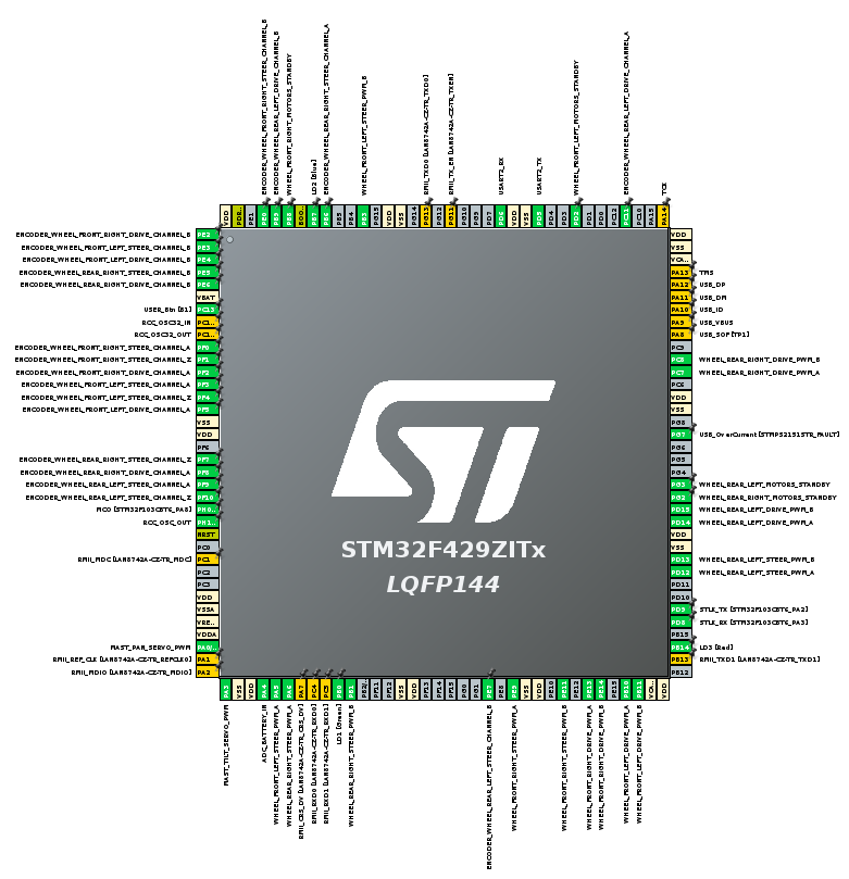
The green pins have a function assigned to them and need to be connected. You can see that there are maybe 50 of these pins.
The task is now to find these pins on the NUCLEO development board that looks like this.
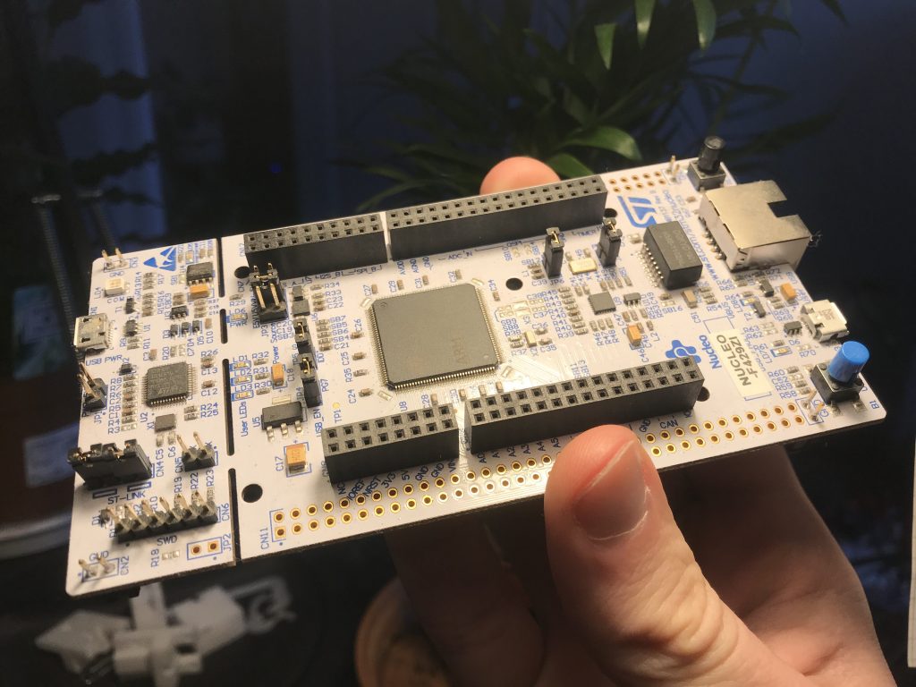
This is usually done by looking up the position of the pins on schematics that are provided by the manufacturer. Below you can find an example for an Arduino board.
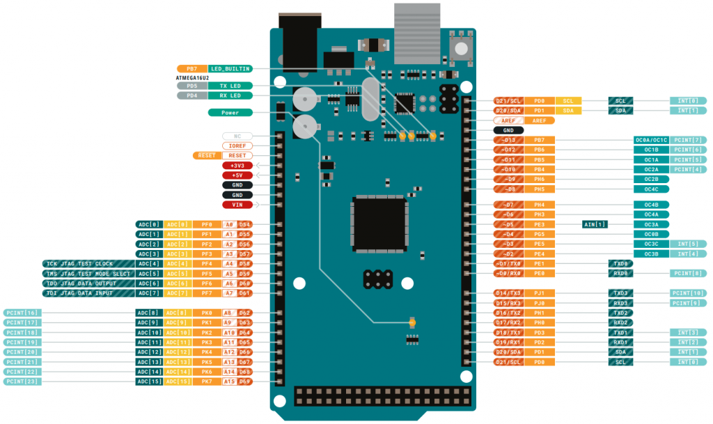
Source: Arduino, (Link) 28.06.2022, modified
Licensed under the Creative Commons Attribution-ShareAlike 4.0 International License (https://creativecommons.org/licenses/by-sa/4.0/)
You can imagine that looking up 50 pins on this schematic takes time and is error prone. That’s why we now come to…
The solution
To find a pin on a board it would be really helpful to be able to simply type the pin name into a search bar and the computer would show you where the pin is. Therefore this is exactly what I’ve created. It’s called the PinFinder. So how do you use it?
The first step is to choose your micro controller from an ever increasing selection of different micro controllers. If you can’t find your micro controller you can also create your own custom layout but more on that later.
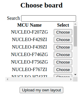
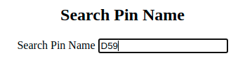
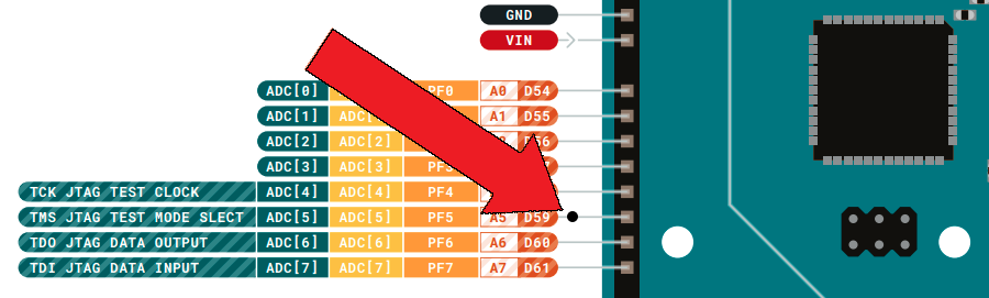
After that you can simply type in the pin name you are searching for and the program will show you where it is located.
Can we do better?
You might think now: Well this is all nice and good but still it seems like a lot of work. And I agree. That’s why you can go one step further. It is also possible to provide a .csv file that describes all the different pins you have on your micro controller and their associated function. It might look like this:
"Position","Name","Label"
"1","D59","ENCODER_A"
"2","D62","ADC1_IN"
"3","D66","PWM1_OUT"
"4","PF6","SOME_PIN_THATS_NOT_ON_THE_HEADERS"
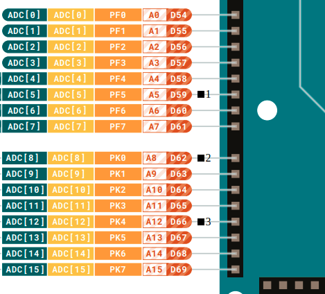
There is an additional input field in the PinFinder where you can post this .csv data. If you do that, it will show you the position of all these pins and their associated function. This makes it very easy to see where you have to connect which pin. The location of pins is shown as black boxes with IDs next to them.
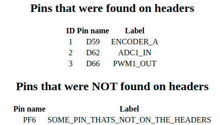
And below the hardware layout you can find a table that tells you which pin has which function. It also tells you if you have a pin assigned that can not be found on the header.
It gets even better with CubeMx
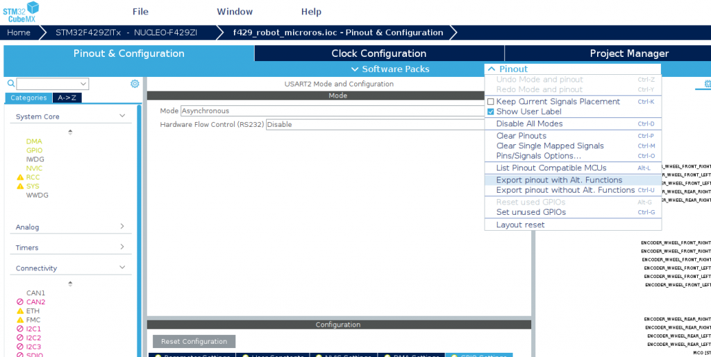
And now for a special treat for all the STM users out there. It is possible to create this .csv file directly from CubeMX. That means you don’t have to create it yourself but let CubeMX do the work for you. In CubeMX go to „Pinout & Configuration“, then select the „Pinout“ dropdown, and choose „Export pinouts with Alt. Functions“.
Custom layouts
As there are quite a lot of boards available it might happen that the board you use is not available in the PinFinder yet. Or maybe you have created your own PCB. That’s why it’s also possible to create your own layout and use it just like the other ones.
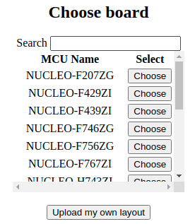
To create your custom layout you have to provide two things:
- an image with your layout
- the name and position of the pins on that layout.
The name and position are provided as a .json file. It might look like this:
{
    "name": "Custom",
    "headers": [
        {
            "name": "Left",
            "pins": [
                "GND", "GND", "+3V3", "VIN"
            ],
            "horizontalNotVertical": false,
            "xBasePosition": 78,
            "yBasePosition": 165,
            "type": "single",
            "pxPerPinStep": 46.5
        },
        {
            "name": "Bot",
            "pins": [
                "PA1", "PA2", "PA3"
            ],
            "horizontalNotVertical": true,
            "xBasePosition": 169,
            "yBasePosition": 414,
            "type": "single",
            "pxPerPinStep": 62
        },
        {
            "name": "Right",
            "pins": [
                "PB1", "PB2", "PB3", "PB4", "PB5", "PB6"
            ],
            "horizontalNotVertical": false,
            "xBasePosition": 232,
            "yBasePosition": 163,
            "type": "double",
            "pxPerPinStep": 22.9,
            "pxBetweenDifferentSidesOfHeader": 85
        }
    ]
}
Once you have inserted these two things, you can click insert and the layout will be added to the list of available layouts. From there you can simply select it and use it just like the other ones. On the PinFinder you can find hints what the different values in the .json file mean and some tips how to set it up. I’m aware that this setup procedure is a somewhat laborious task so I’m looking into other options that are more user-friendly, stay tuned!
I’m also working on options so that you can send your finished layouts to PinFinder so that it can be added to the official list of micro controllers. In this way we can extend the PinFinder and support more and more chips.
Final thoughts
I hope that the PinFinder can serve you well and help you with your projects. I already used it in a project and it made life considerably easier. Until next time.
A short notice on the design and layout of the PinFinder: Currently the PinFinder is still under development so the way it looks and is structured might change in the future. The general idea will stay the same though.